
Servo motor is a brush less dc motor used especially in robotics applications, RC (remote controlled) plane to position the wing flaps orin cars for steering. Servo motor is comprised of these components –
1. Potentiometer
2. Gears
3. Drive circuit
4. DC Motor
Servo motor takes +5V Input, however it is advised to refer the product manual of the servo motor in consideration. For eg: Hi-Tech HS-311 Servo motor allows voltage from 4.6v to 6v. Maximum output power being at 6v.Ground connection is represented by black wire. Making wrong connections sometimes can damage the servo motor( the circuit is fried if wrong connections are made) therefore it is recommended that proper connections be made while using servo motors with embedded systems or electronic circuits.The third connection is the pulse width modulation (PWM), the digital signal applied to pin controls the position of the servo motor.
What’s inside the servo?
The potentiometer is directly connected to the shaft of the motor. As the motor rotates, the potentiometer’s resistance changes, so the control circuit can precisely regulate how much movement there is and in which direction.
When the shaft of the motor is at the desired position, power supplied to the motor is stopped by the control circuit. If not, the motor is turned in the appropriate direction. The desired position is sent via electrical pulses through the signal wire. The motor’s speed is proportional to the difference between its actual position and desired position. So if the motor is near the desired position, it will turn slowly, otherwise it will turn fast. This is called proportional control. This means the motor will only run as hard as necessary to accomplish the task at hand, a very efficient little guy.
When these servos are commanded to move, they will move to the position and hold that position. If an external force pushes against the servo while the servo is holding a position, the servo will resist from moving out of that position. The maximum amount of force the servo can exert is called the torque rating of the servo. Servos will not hold their position forever though; the position pulse must be repeated to instruct the servo to stay in position. It is possible to command an RC servo to move over its entire range with a function generator set to a constant (say10%) duty cycle by changing only the frequency.
0o 90o 180o
Servo programming in ARDUINO
#include <Servo.h>

Servo myservo;  // create servo object to control a servo

intpos = 0;    // variable to store the servo position

void setup()

{

myservo.attach(9);  // attaches the servo on pin 9 to the servo object

}

void loop()

{

for(pos = 0; pos< 180; pos += 1)  // goes from 0 degrees to 180 degrees in steps of 1 degree

{

myservo.write(pos);              // tell servo to go to position in variable ‘pos’

delay(15);                       // waits 15ms for the servo to reach the position

}

for(pos = 180; pos>=1; pos-=1)     // goes from 180 degrees to 0 degrees

{

myservo.write(pos);              // tell servo to go to position in variable ‘pos’

delay(15);                       // waits 15ms for the servo to reach the position

}

}
Driving the servo motor using a function generator
A three-wire DC has three input wires: the red wire is usually connected to the power supply, the black wire is usually connected to the ground and the white/yellow wire is usually connected to the controlling signal. One of the simplest way to test/drive a servo motor is to generatea pulse using a function generator. The pulse can be be generated using the square wave function of the function generator. You should adjust the amplitude of the square wave such that it matches the power supply of the servo motor.
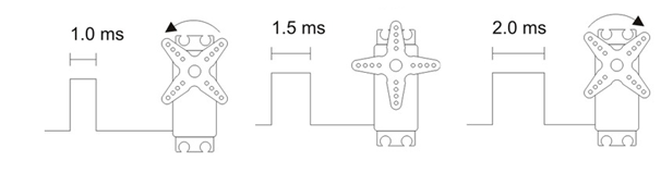
Once you have adjusted the amplitude of the square wave pulse, you can adjust the width of the pulse train by adjusting the frequency of the signal. For the servo motor that we are using, the neutral point (the pulse width at which the servo stays at 90 degrees) is about 1520 microseconds(us) or 1.52ms. Any pulse width narrower than 1.52 ms will cause the servo to move to a position less than 90 degrees and vice versa. Note that servo only turns between 0 and 180 degrees if it is not modified. This corresponds to about 0.8ms to 2.5ms of pulse width. Make ensure the pulse width that you use is in within this range.
For a servo motor modified to rotate continuously, the servo will not turn at the neutral pulse width but it will turn clockwise continuously if the pulse width is less than the neutral pulse width and anticlockwise if the pulse width is larger than the neutral pulse width. (the pulse width has to be within the range mentioned above).
Modifying (hacking) a Servo Motor to a contentious rotation servo
As mentioned in the previous section, the servo motor rotates less than 360 degrees. They can, however, be modified into continuously revolving DC gearhead motors to drive robots’ wheels. The changes are quite easy to do, if you follow the instructions in this section.
The theory behind this modification is to make the servo think that the output shaft is always at the 90 degree mark. This is done by removing the feedback sensor, and replacing it with an equivalent circuit that creates the same readings as the sensor being at 90 degrees. Thus, giving it the signal for degrees less than 90 degrees will cause the motor to tuen on full speed in one direction. The signal for degrees greater than 90 degrees will cause the motor to go the other direction. Since the feedback from the output is disconnected, the servo will continue in he appropriate direction as long as the signal remains.
The result of this is a really nice compact gearhead motor with built in electronics. The interface to this motor unit is a 1 wire control line, +5 volts for pwer, and a ground. As for the details, there are actually only two modifications to make to the servo,
1. Replace the position sensing potentiometer with an equivalent resistor network
2. Remove the mechanical stop from the output shaft
You will need a few supplies to do the modifications:
1. smallphilips screwdriver for opening the case
2. a soldering iron
3. adesoldering pump or solder wick for removing the poteniometer
4. a sharp knife or wire cutters for removing the mechanical stop
5. Two 2.2k resistors (actually, anything between 2.2k and 3.3k will work, as long as they are equal values)
Here are the steps for the modifications.
1. Open the case by removing the 4 screws located at the bottom of the servo. The bottom plate should come off easily. Remove the top of the case. You will find a set of gears under the top case, a several blobs of white grease. Try hard to save the grease by increasing it on the gears.
2. Be careful to note how the gears arranged, and remove them from the top of the servo. You can place them as they are supposed to sit. The large fine tooth gear in the middle does not need to be removed.
3. Locate and remove the two small philips head screws on the the case near one of the shafts. These screws go through the top case and into the drive motor..
4. Next, you need to remove the circuit board carefully from the case (Beware not to break the connecting wires when you do this). Very carefully pry ip on opposing corners of the circuit board. (You can probably use a screwdriver to help you to do this.) The board should slide out with the motor and potentiometer attached.
5. Now for the actual modifications. First, you will nedd to desolder the potentiometer from the board.
6. Once the pot has been removed, you need to wire in the resistor network in its place. To do this, place the resistors side bt side and twist one pair of leads. Solder them together, but leave one of the leads long enough to make a 3 wire part. Then replace the pot with this 3 wire pot.
7. Now, reassemble the circuit board into the case.
8. Before reinstalling the gears, you will need to modify the gear with the output shaft so that the mechanical stop is removed. The mechanical stop is a small tab of plastic on the lower gear surface. This should be cut down flush with the surface by using a wire cutter or a sharp knife. Try to get all the tab removed.You should also remove the little plastic ring on the motor shaft as well.
9. Replace the gears as they were when you took the motor apart, replace the top of the case, the bottom plate, and the two screws.
The motor should now be able to turn all the way around.
You’ve made some good points there. I looked on the net for more information about the
issue and found most individuals will go along with your views on this website.
Hi admin, i see your website needs fresh posts.
Daily updates will rank your website in google higher, content is king nowadays.
Hi, i really enjoy your articles and i have just analyzed your backlinks.
You need more authority links in order to rank.
Best backlinking strategies in 2015 are backlinks pyramids and private blog
networks. You can hit google’s top 10 easily.