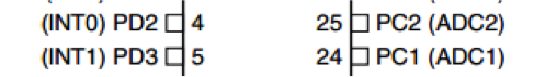
In the following session I am going to explain how to implement quadrature encoding in ATmega8 using AVR programming. If you are new to AVR programming refer to this document .Ok, now Let us start by discussing about interrupts. Interrupt call orders immediate attention towards specific Interrupt Service Routine (ISR) by pausing main code. There are two external interrupt pins in PORTD register of ATmega8.
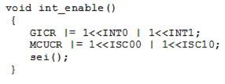
now I like to connect my two encoder channels to INT0 and INT1 of ATmega8 .Now our next task is to call ISR for any logical change on interrupt pins. For this purpose, first I need to activate interrupt pins. It can be done using the following line of code
![]()
Now I like to call ISR for any logical change using the below code.
![]()
The whole code put together will look something like this
Sei () is added to enable global interrupt because without this none of our interrupts are going to work. It’s time to start exploring algorithms to find out direction and velocity. The method I am going to use is based on GRAY code.
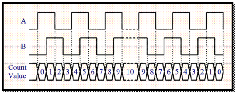
If you observe above waveforms for two consecutive counts, only one channel changes its state while another doesn’t. Now I have tabulated states of waveforms in above figure
| STATE | CHANNEL A | CHANNEL B |
| 1 | 1 | 0 |
| 2 | 1 | 1 |
| 3 | 0 | 1 |
| 4 | 0 | 0 |
If we observe state 1 of channel A and state 2 of channel B, both of them are in the same logic level. Similarly, any other two consecutive states. The above table was obtained assuming channel A leads channel B (assuming clockwise direction). Now for anti-clockwise direction where channel B leads are obtained as follows (just logic levels of both channels get interchanged).
| STATE | CHANNEL A | CHANNEL B |
| 1 | 0 | 1 |
| 2 | 1 | 1 |
| 3 | 1 | 0 |
| 4 | 0 | 0 |
If we do same observation as we did for previous table, will give us that both of them are not in the same logic level. Our immediate task is to use this logic in our code. Since AVR ports are 8 bits and INT0, INT1 are 3rd and 4th bit, first I am going to make them 1st and 2nd bit so that it would be easy to access them.
presentstate = ((PIND & (3 << 2)) >> 2);
From this I want to get the data so that it contains information about only one channel
This line of code presentstate & 1 will give us information about channel A in the leastsignificant bit while on channel B by
(presentstate & 2) >> 1)
Now XOR logic will help me differentiate both directions of rotation.
dir = (previousstate & 1) ^ (presentstate & 2) >> 1);
From this we will be getting value of ‘dir’ as always 1 when it’s rotating in one direction and 0 in another direction. When we put all these lines of code together, we have the following ISR function.
volatile unsigned long count = 0;
ISR (INT0_vect)
  {
  presentstate = ((PIND & (3 << 2)) >> 2);
  dir = ((previousstate & 1)^(presentstate & 2) >> 1);
  if (dir == 0)
    count++;
  else
    count--;
  previousstate = presentstate;
  }
I specially mentioned count as an unsigned long because it doesn’t affect your direction (its range doesn’t contain negative values)
Using the below code I am repeating the same code for ISR of INT1
ISR (INT1_vect, ISR_ALIASOF (INT0_vect));
Now I am going to start a timer for a particular amount of time .After that specific amount of time, timer overflow interrupt occurs and in that ISR I am going to calculate velocity
ISR (TIMER0_OVF_vect)
{
  a=count-oldcount;
  velocity = (a*60)/(PPR*4)/gear/time;
  oldcount = count;
}
Here,
PPR is Pulses per Revolution of base motor
Gear is gear ratio
PPR*4 is Counts per Revolution (CPR)
Value of ‘a’ gives us no: of counts in specific amount of time for which timer is on. So, ‘a/time’ gives us Counts/Sec. Now using PPR we have converted that into rev/min. Finally, we are going to get the velocity of output shaft along with the direction of rotation.
For full code download the following document.
main
We will be back soon with PID control of velocity of the motor.