Relays are simple switches which are operated both electrically and mechanically. Relays consist of an electromagnet and also a set of contacts. The switching mechanism is carried out with the help of the electromagnet. There are also other operating principles for its working. But they differ according to their applications.
Generally, it takes only a relatively small amount of power to switch ON/OFF a relay but the relay may be able to control a high power device, which makes relay an important device. Electrical devices which contains a microcontroller or some other kind of logic circuit are more likely to have a relay inorder to interface the control circuit to the electrical appliance. For example, we can find a relay inside a washing machine, air conditioner, timer switches etc. In essence, a relay will insulate the control circuit from the controlled circuit.
Two main types of relays electromechanical relays and solid-state relays. An electromechanical relay comprises an electrical switch which can be switched on and off by magnetizing and demagnetizing the electromagnet inside the relay whereas a solid-state relay is using a semiconductor device to perform switching. Let us look at some specifications of electromechanical relays.
Specification
evident from the schematic representation shown above, a relay contains an electromagnetic coil and a switch. For understanding how a relay works, let us consider that we are using a relay with the following specification.
COIL DATA :
- Nominal Voltage : 6 V DC
- Pick-Up Voltage : 4.5 V DC
- Maximum Voltage :7.8 V DC
- Coil Resistance : 100 ohm
CONTACT DATA :
- Contact Rating : 1A 240 v AC / 30 v DC
- Maximum Switching Voltage : 240 v AC / 30 v DC
- Maximum Switching Current : 5A
- Maximum turn on time : 10 ms
- Maximum turn off time : 5 ms
Most of the details given above are self explanatory. Note that the specification for a relay is divided into two sections coil data and contact data. The coil data is the electrical specifications for the electromagnetic coil part whereas the contact data is the specifications for the switching part (to keep it simple) of a relay. 4.5 V Pick Up Voltage means that the relay would sense a voltage as low as 4.5 V as a logic ‘HIGH’, even though the nominal voltage is 6 V. One of the most important thing to take care of when selecting a relay is the maximum switching current. We always have to make sure that the switching current of our circuit is well below the maximum switching current rating of the relay so as the relay wont get damaged. Now lets look at the working relays.
Working
An electromechanical relay is controlled by applying a logic HIGH/LOW between the v1 and v2 terminals of the relay. When we apply a HIGH between the input terminals, current will flow through the coil which will magnetize it. The magnetized coil pulls the switch closed. Till now we were discussing about the input terminal. So what about the switch stuff?? Relays are designed to have either of the two switch positions namely, Normally Open(NO) and Normally Closed (NC).
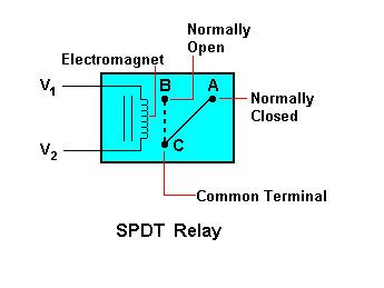
For an SPDT relay, when no voltage is applied at the input of the relay, the Comonnected to the NC pin. ie., when the relay is demagnetized, the switch will be in the Normally Closed position whereas when the relay is magnetized, the switch will be in the Normally Open position as the magnetized coil attracts the switch from position A to B(see the figure above). The switch has a spring which causes the switch to switch back from B to A once relay is demagnetized.
Solid-state relays(SSR) control the high power device in response to the voltage difference across the LED by using a power MOSFET as the switching device. SSRs can replace many types of low power electromechanical relays. It uses opto-coupling to provide complete electrical isolation between control circuit and power circuit. The light from the LED activates the photovoltaic cells and produce voltage enough to switch on the MOSFET. When the input control is LOW,
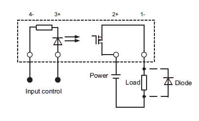
Source: http://www.futurlec.com/Relays/SSR3A48D05.shtml
Different Types of Relays
Electromechanical Relays:
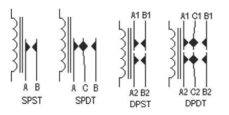
- Single Pole Single Throw(SPST): Comprise 4 terminals. Two terminals are used as coil terminals and other two can be used to connect the power circuit.
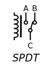
Single Pole Double Throw(SPDT): Comprise 5 terminals two for coil one for common terminal(C). A and B terminals can be used to connect two power circuits with terminal C as common terminal. - Double Pole Single Throw(DPST): Comprise 6 terminal two for coil and other four for connecting two power circuits. In other words it contains two SPST relay in one package.
- Double Pole Double Throw(SPDT)- these types of relay comprise of 8 terminal two for coil and another two as common points(C1 and C2) and rest for connecting four power circuits. i.e., two SPDT relays are connected in one package.
Source:http://www.engineersgallery.com/working-relay/
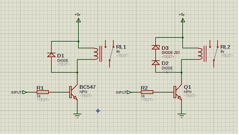
Practical Circuit
Now lets see how we can wire up a circuit using an electromechanical relay. Since a microcontroller or any other logic ICs may not be able to supply enough current required to magnetize the relay coil fast enough, we always use a transistor as a switch to interface our control circuit to the relay.
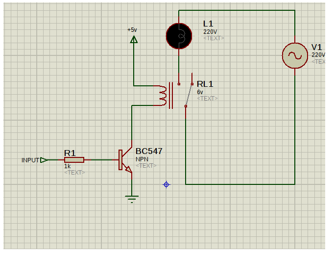
The circuit itself is self explanatory. Don’t get scared seeing the transistor in the circuit. We always like to understand it in the simplest form. Isn’t it?
- When we apply a HIGH at the input of the circuit, the transistor turns ON. This provides a low resistance path to the ground. Which means that now our relay is connected to 5 v at one of its input terminal whereas the other terminal is grounded. This will energize the coil and completes the power circuit.
- When we apply a LOW at the input of the circuit, the transistor turns OFF. Therefore, the transistor will be in ‘open’ state due to high impedance. Therefore no current will flow through the relay coil and therefore, will remain demagnetized.
Flyback diode
I hope you remember that an electromagnet is an inductor. What is the important property of an inductor? An inductor wont allow the current flowing through it to suddenly change. Consider that the input is suddenly pulled LOW. The current flow through the relay should suddenly stop due to the high impedance provided by the transistor. But the inductor tries to keep the same current flowing through the relay coil, which causes the voltage across the coil to increase suddenly. This
phenomena can be explained using the equation
V = L(di/dt)
Anyway its out of our scope for the time being. This creates a spike(a sharp but short voltage) which can reach hundreds or thousands of volts which is more than enough to damage all the electronics that we had in our circuit. In order to avoid this pitfall, we something called a flyback diode.
The circuit is just a diode which is connected across the relay input such that the diode is normally reverse biased. The diode provides path for the energy stored in the relay coil to be dissipated quickly. Moreover, the diode also clips the voltage across the coil at 0.7v protecting the rest of the circuit. A recommended add on to this circuit is to add a zener diode in series with the diode. This will help use up the energy stored in the relay coil quicker than before.