Hardware
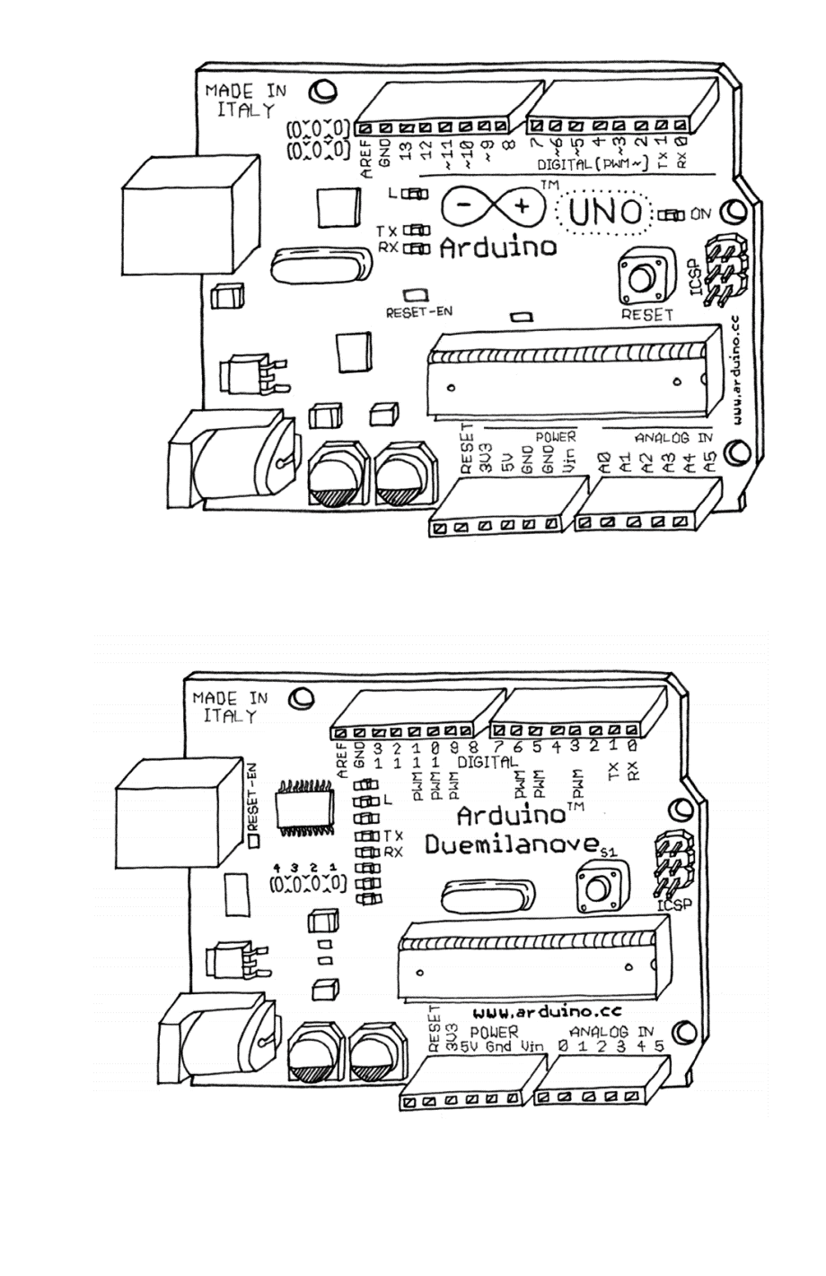
We will first concentrate on hardware part i.e. on the pin configuration of arduino board. Arduino contains a microcontroller, I/O ports, power supply unit, USB port etc. Microcontrollers have ROM, RAM, I/O ports on a single embedded chip.
Digital pins:
There are 14 digital pins available. They can be used as input or output pins according to sketch you upload. Among them 6 are PWM (pulse-width modulation) pins (3, 5, 6, 9, 10, and 11). They are represented by “~” symbol on the board
Analog pins:
There are 6 analog pins, A0, A1, A2, A3, A4, A5. These dedicated pins take analog values as an input (voltage values from sensor) and then converts it to numbers from 0 to 1023 using a 10 bit ADC(analog to digital converter). These 6 pins are the analog input pins and the PWM pins that are mentioned above are the analog output pins.
(We know that all the microcontrollers and microprocessors work on binary language i.e. by using only two numbers – 0 and 1 representing HIGH and LOW. All of these devices work on the digital input by handling digits and not on the integers. Practical data is analog and not digital so we need to covert the analog data into the digital data for further processing.)
Power supply pins:
GND, 5V and 3.3V, there are three different ways to power the IC, through power jack, by using USB which is connected to your PC and by using battery in the Vin pin.